In our workshop we create many different things on our milling machines. Some of them are tests for you and others are ideas that often come late at night. We have decided to share our projects with you so that people who already have CNC milling machines can get inspired, new users can gain knowledge and experience and people who are thinking about purchasing can learn a little more about our CNC machines.
This is the first article to launch a new series of tutorials! Let's go!
Laptop base v1
In this first article we will show you how using a CNC milling machine and V-SLOT profiles, you can create an interesting laptop stand at low cost. Of course, every laptop is different (it has different dimensions) so based on our design it is worth to check if your equipment will fit and possibly change the design to suit your needs.

What will we need?
Here, too, we would like to say that each project will contain a list of necessary elements, which we will place both in this article and we will also link you to a google sheet where you will find links to products.
Materials we used for the stand:
- 10mm MDF plate (here we recommend to you a material stiffer than a piece of wood or thicker plastic board. MDF will be used here because it is a good material for milling machines, especially for beginners. . . in a word, it forgives much)
- 2 x 37 cm long aluminium profile V-SLOT 2020
- 4 x 20 mm flat headed allen screw
The device and accessories for making a stand:
- Milling machine with working area min. 30 x 30 mm - we made a stand using a LEAD CNC 1010
- Flat milling machine 3mm
- Screwdriver M5
- Sanding paper
- Wallpaper knife
- Allen key
Design in Fusion 360:
The first stage of the project is to move our idea from the head to the graphics program. As you probably know, we design at Fusion 360 Autodesk. After starting the program, we start the design process. We will not describe the whole design process, but will present it to you in the form of a video on our YouTube channel - you will find the video at the end of this article. The rack model consists of 2 walls which are connected to each other by V-Slot profiles and imbus screws.
You can download the profile models from our website by clicking on LINK and the side walls are a matter of our imagination.
After creating the 3D model, we go to the Manufacture tab where we create the process for the milling machine. When everything is ready, save the file from G-CODE and upload it to the OpenBuilds Control router software.
Milling:
It will take us about a year to make the elements we have designed on the milling machine. 12-15 minutes. We start by attaching the MDF to the router table. There are many ways of fastening and as you will see in the recording we used several wood screws to fix the MDF which we will process on the MDF which is the base of the LEAD CNC 1010 router. We will mill with a 3mm diameter flat milling cutter.
Main milling setting:
- 3mm flat milling cutter
- DeWalt spindle D26200 set at the lowest speed (1) ~16,000 rpm
- Average speed of the axis feed: 2400 mm/min (you can easily increase this speed when using a good milling cutter)
- Single pass depth (DOC): 2.5-3mm
- Point 0 for the X/Y/Z axis is the left bottom edge of our material
When we install the cutter, we start the milling machine, using OpenBuilds Control software we set the point 0. 0. 0 for each axis, raise the Z axis by 15-20 mm and we can start the spindle. It is always worth to use the Check Size function, thanks to which the milling machine will determine the area in which it will work by moving around its perimeter. REMEMBER TO KEEP THE CUTTER ABOVE THE MATERIAL, OTHERWISE THE CHECK SIZE FUNCTION MAY CAUSE THE CUTTER TO MAKE A CIRCUMFERENTIAL MOVEMENT, DESTROYING THE MATERIAL.
When everything is as planned, we make sure that the material is well fixed, the spindle is properly fixed in the milling machine holder, our safety button is at hand and we can start working.
Remember to take all precautions when working with the milling machine!
You will also see the milling process in the video and before that, one small comment. At some point in the film you will see how the cut-out element pops up and the milling machine has not finished its work yet. This was our mistake, because we were incorrectly occupying the material and left the Z axis a little too low when setting the 0 position. It is worthwhile to glue the MDF board from underneath, e. g. Use the paint tape or use the Z-axis position sensor to correctly determine the zero point for the Z-axis. You can also use the TABS function in the Fusion 360 software, which will leave small grips between our actual workpiece and the material in which we are milling.
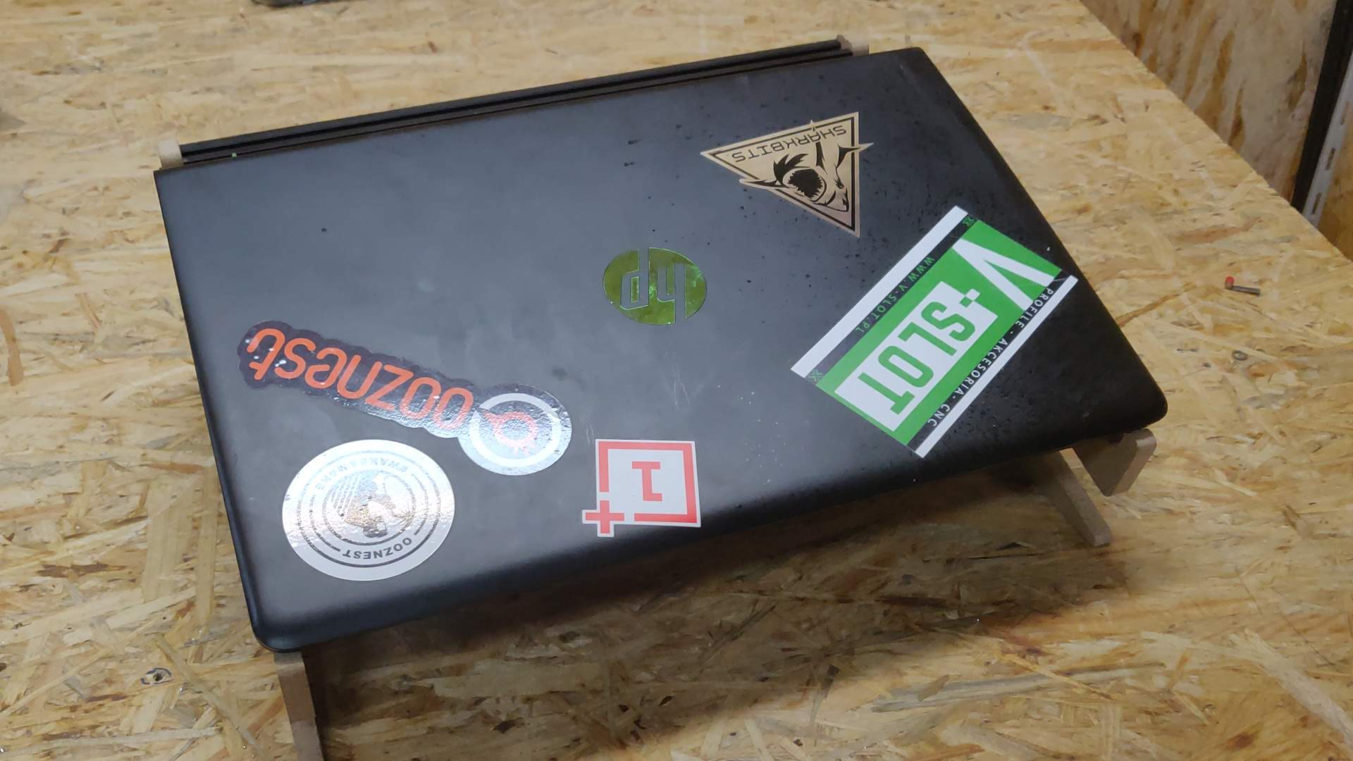
After milling, we clean our model with e. g. sandpaper and a knife.

We also used black spray to paint the disc: